How it applies when using a rotating spaceship to simulate gravity.
This article is adapted from a talk I gave to the Western Colorado Astronomy Club. I was not aiming for a thesis for a Masters Degree but as an informal, fun, but informative, article. It is intended for general audiences but does include some algebra. For a more detailed breakdown of the math involved see my article on “Calculating Angle and Velocity of Vectors in a Rotating Filed.” The illustrations and models used are intentionally crude for simplicity. I am in the process of improving it so expect changes occasionally (I did find some minor math errors due to rounding off decimals and have made a change to the apparent motion of a falling object). This is the most viewed of all of my articles. I don’t know how to blog yet so check out my home page for anything new. Newest update was Feb. 2, 2026.
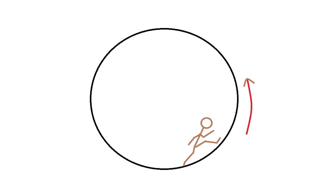
Many movies and science fiction novels have described rotating spaceships to simulate gravity. One of the first movies to demonstrate this was “2001: A Space Odyssey” by Stanley Kubrick (See Appendix 2 for specifications and comparisons). They showed a large doughnut shaped ship that rotated. It has become the definitive shape when people picture a ship simulating gravity. He also envisioned a circular living area inside a round command module that rotated, which actor Gary Lockwood used as a running track. Arthur C. Clark also used a barrel shaped ship in his novel, “Rendezvous with Rama.” All would work but there are some interesting problems that the Coriolis Effect creates.
While researching for this article I have found that actually using a rotating ship to simulate gravity could create some surprises and be a little dangerous but first, a little background.
The Coriolis Effect was first posited by Giovanni Battista Riccioli along with his assistant Francesco Maria Grimaldi. Riccioli was an Italian astronomer and a Catholic Priest. He argued that a canon fired directly north would fall east of its target due to earth’s rotation. The rotation being faster toward the equator than toward the North Pole. Since this was not detected he argued that Earth did not rotate. In 1691, canons were not powerful enough to propel a ball far enough for the effect to be noticeable. His argument was correct but his conclusions were premature.
The same conclusion came from Claude Francois Milliet Dechales in 1674. Then in 1749 Leonhard Euler, a Swiss mathematician developed the acceleration equation that describes the effect. He may have had it named after him if he wasn’t interested in almost literally everything else from mathematical notation to music theory. A few years later in 1778, Pierre-Simon Laplace described it in his tidal equations on its effects on the oceans.
It fell to Gaspard-Gustave Coriolis in 1835 to finally lock down the formula. Coriolis was trying to calculate the energy yield of machines with rotating parts as in waterwheels. It became known as the Acceleration of Coriolis and later the Coriolis Force. The effects of the force became the Coriolis Effect.
The formula is not important to this thesis but will be shown in Appendix 1. We will be focusing on the effects to an astronaut who is standing inside a rotating spaceship.
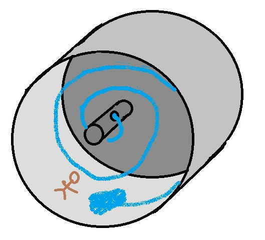
For simplicity we will be using a circular tube such as a barrel. The barrel will be rotating counter clockwise in our model, represented by a simple cylinder.
To begin we will assume the “ship” has already accelerated up to speed. As it started from its static position, our little astronaut would have been floating freely inside. Hopefully she would have been holding onto the floor so she would stay attached to the “floor” as it rotated up to speed. As our ship attains its final velocity (see Appendix 1 for velocity of rotation to achieve desired G-Force or Earth gravity equivalent) our astronaut is now feeling a force that seems to be holding her to the inside of our ship just like gravity. If you have ever flung a bucket of water in a circle up and over your head like a windmill and you swung it hard enough for the water to stay inside, you now understand the effect. Our problem is, will she be able to walk, run, sit, stand, or throw a sandwich to a fellow astronaut just like she was on Earth? Short answer is no. Why?
Force on Subject in Ship
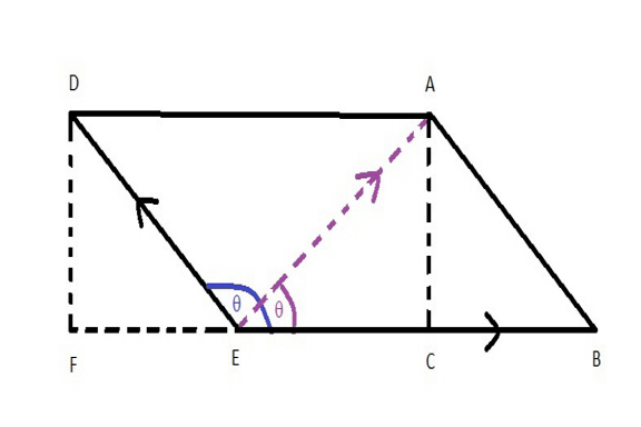
Let us breakdown what is causing the force that is holding our astronaut to the “floor.” Our astronaut is rotating with the ship so we can basically consider that motion as a constant. No acceleration to our ship is needed to keep it moving at our constant rotation. We will assume our ship and astronaut would continue at this rate for eternity. Looking at this from our astronaut’s view (and picturing our astronaut as facing away from us), the ship’s rotation is propelling our astronaut in a circle. That motion is retarded by the shape of the ship, which is a round drum in our example. The sideways motion of our astronaut that is retarded by that shape is forced to constantly curve in what would appear to that astronaut as a motion that is to her right and up. That upward motion would not feel like an upward motion but as a push up on the feet from the floor. This pushing from below would be similar to what is experienced in an elevator. Picture it as the movement to the right is forced to stop that direction and move up. The force that is making that curve would average out to a 45 degree angle to the 90 degree turn. That 45 degree angle points exactly to the hub of the circle. Below is a graphic representation of this force which is actually an acceleration. A constant change in direction from a varying force is an acceleration. Blue arrow is the rotation, purple represents the change in direction and green the average or net force.
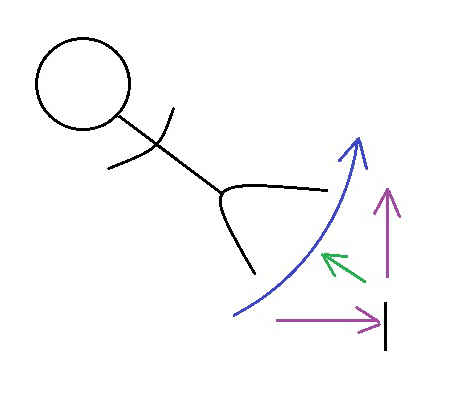
Again, this is just a graphic representation of what our astronaut would experience. You are only feeling “gravity” because of a push up on your feet. The net result of this push (acceleration) negates the circular feeling of motion, causing the net force to be a straight line to the hub or center of our rotating ship. This is an important point. The rotation of the ship is causing an acceleration to our astronaut. This acceleration is transforming the rotation of our astronaut to a push from below. This is a constant acceleration where the net force is toward the hub and this force negates the feeling of the circular motion. If that force is stopped, our astronaut would continue along the last direction of motion which would be at a right angle to the line from the floor to the hub. This demonstrates that the acceleration on the astronaut’s feet is toward the hub, not at an angle to the direction of motion.
Our astronaut is experiencing artificial gravity that feels normal. How about moving around and interacting with other moving objects? Will it be exactly as we experience here in Earth’s gravity field. Let’s explore some basic motions. We will start with a simple action before moving on to more complicated issues. I will delve into the mathematics for this first issue to demonstrate how I achieved my findings.
Drop
What if you drop something? How will it “fall?” Will it fall? Yes. Whatever you are holding is going around in a circle but suddenly it loses its circular motion and will move in a straight line in whatever direction it was going. It just lost one of its motions, ending the acceleration. Before the drop, your hand was providing the two motions and the acceleration.
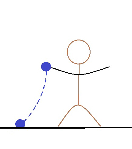
You drop the ball to the side of your body in the ship. In our drawing, it would land to the LEFT of the person who dropped it or backwards of the direction of motion. Here is a diagram of what is happening.
So what is happening?
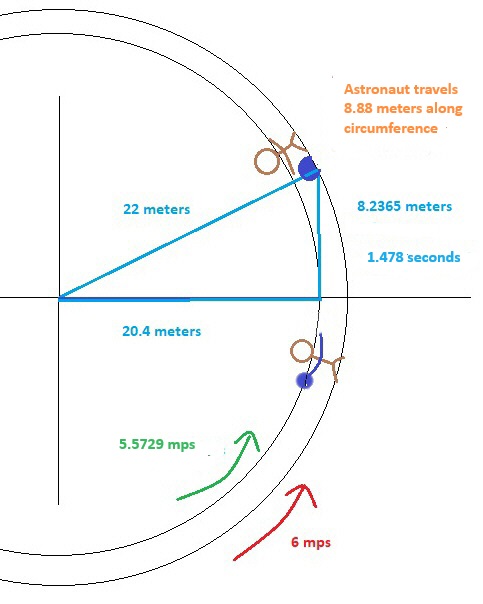
Let’s set some parameters to our spaceship. Hub to floor, 22 meters. Ship is rotating once every 23 seconds. Ball starts fall at 1.6 meters above the floor. In our ship, the ball is traveling in a circle with our astronaut but not at the same rate. Her feet are moving at 6 meters per second (r = 22 meters x 2 x π = 138.23 meters / 23 seconds for each revolution = 6 meters per second or MPS). 1.6 meters above when she drops the ball, the ball is moving at a slower 5.5729 MPS (same rate of rotation but less distance to travel, 20.4 x 2 x pi = 128.1769803 Meters, divided by 23 seconds = 5.572912185 MPS). The force up from the floor is on her body and the ball as long as she is holding it. When she lets go, that push is removed and it continues in a straight line (compared to the outside universe) at 5.5729 MPS. That straight line is parallel with the floor only when she lets go. Then she curves up from the rotation. To her, the ball would fall with an acceleration similar to how it does on Earth. It would fall at 5.5729 MPS but in a curved line just like the above illustration. Since her feet are traveling at 6 MPS and the ball at 5.5764, it would fall behind making it look like it curved opposite of the direction of rotation (See Appendix 1). It would appear to her that the ball is “falling” at a little over one meter per second as an average.
Here is the breakdown. I will round off when estimating but the exact figures are given for performing the calculations. The equation is the Pythagorean Theorem: a2 + b2 = c2. If the radius of the ship is 22 meters, rotating at 6 meters per second and the ball is dropped 1.6 meters above the floor, then the ball would be moving at 5.5729 Meters Per Second, travel 8.2365 meters before hitting the floor and fall for 1.48 seconds. (222 – 20.42 = 67.84 Meters (M). √67.84 = 8.236504113 M. 8.23650113 / 5.572912185 MPS = 1.477952793 seconds). To our astronaut it would travel a little over the 1.6 meters in 1.48 seconds (a curved path) at about 1.08 MPS. Also it would land .44 meters behind her.

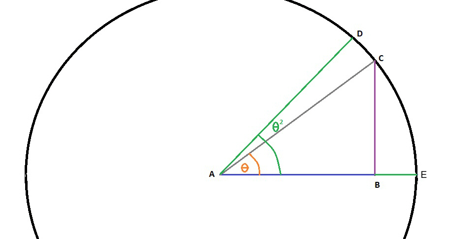
This is how to calculate the distance the ball will land behind the astronaut.

The orange “theta” is the angle made by the ball as it landed on the “floor,” compared to where it was dropped. The green “Theta” is the angle made by the distance the “floor” has rotated (not necessary for our calculations at this time). After calculating the distances and times in the above example, then use this diagram and following equation:
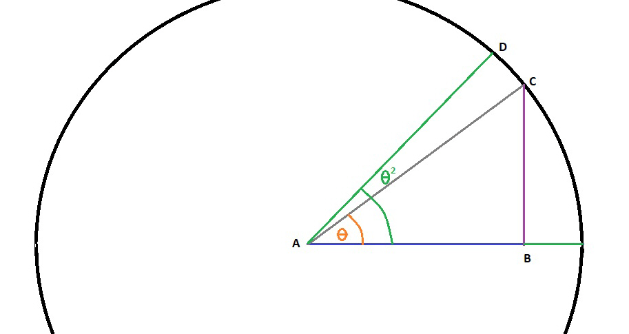
Line AB = 20.4 meters (M). Line BC = 8.236504113 M. Line AC = 22 M. Tan A (orange theta) = BC / AB = .403750202.
To find how far behind the ball lands behind our astronaut, we need to find Theta A in degrees.
Tan A = .403750202 = Theta A = 21.98640302 degrees (use a calculator or a tangent chart). 360 degrees / 21.98640302 degrees = 16.37375607. Circumference = 138.2300768 Meters. 138.2300768 M / 16.37375607 = 8.442172719 Meters. The ball lands about 8.44 meters along circumference from point of drop. Rotation of 23 seconds / 1.477952793 seconds = 15.56206674. 138.2300768 M / 15.56206674 = 8.88250122 M, the distance traveled along circumference by our astronaut. 8.88250122 – 8.442172719 = .440328501 M. The curved line CD = .440328501 M. The ball lands about .44 meters behind her hand in the rotation. The .44 meters is along the curved floor, not in a straight line.
Update. I have been curious about the arc of the falling ball. It is an acceleration from her point of view, due to the curvature of her motion, and would mimic a gravitational acceleration in that the curve away from her, would increase as the ball approached the floor. This would look like an acceleration to the astronaut, even though the ball is traveling at a constant velocity.
You can also calculate the green theta “A” to get the angle our astronaut travels during the drop which will also help you to find the direct line form the astronaut to the ball in a straight line. This would be helpful for calculating precise distances in a large ship. To find the angle traveled by the astronaut: Rotation of 23 seconds / 1.477952793 seconds of travel time = 15.56206674. 360 degrees / 15.56206674 = 23.13317415 degrees (compared to 21.98640302 degrees of rotation before the ball hit the floor). We were not interested in the angle the astronaut had rotated but I give it here for those who are interested.
Here are a couple of stopmotion animations I created to show this effect. I haven’t done any of this type of animation in a couple of decades but it was fun to play with stopmotion again. (No comments on the simplicity, please. My sense of humor is at work!).
From the perspective of our astronaut.
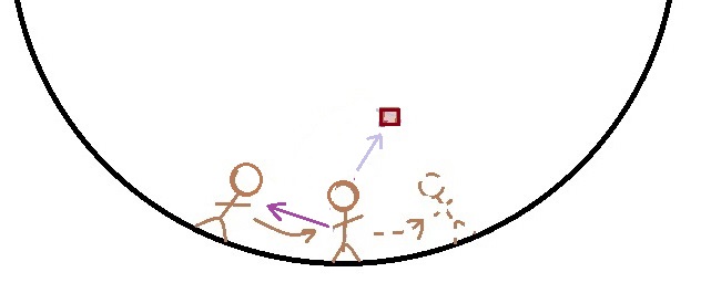
Throw
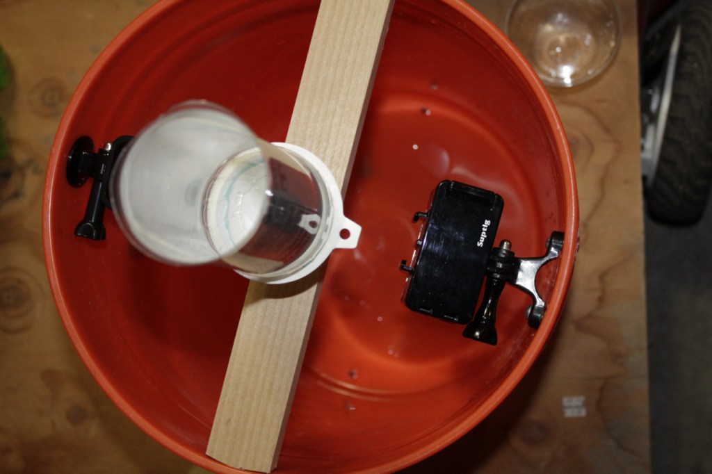
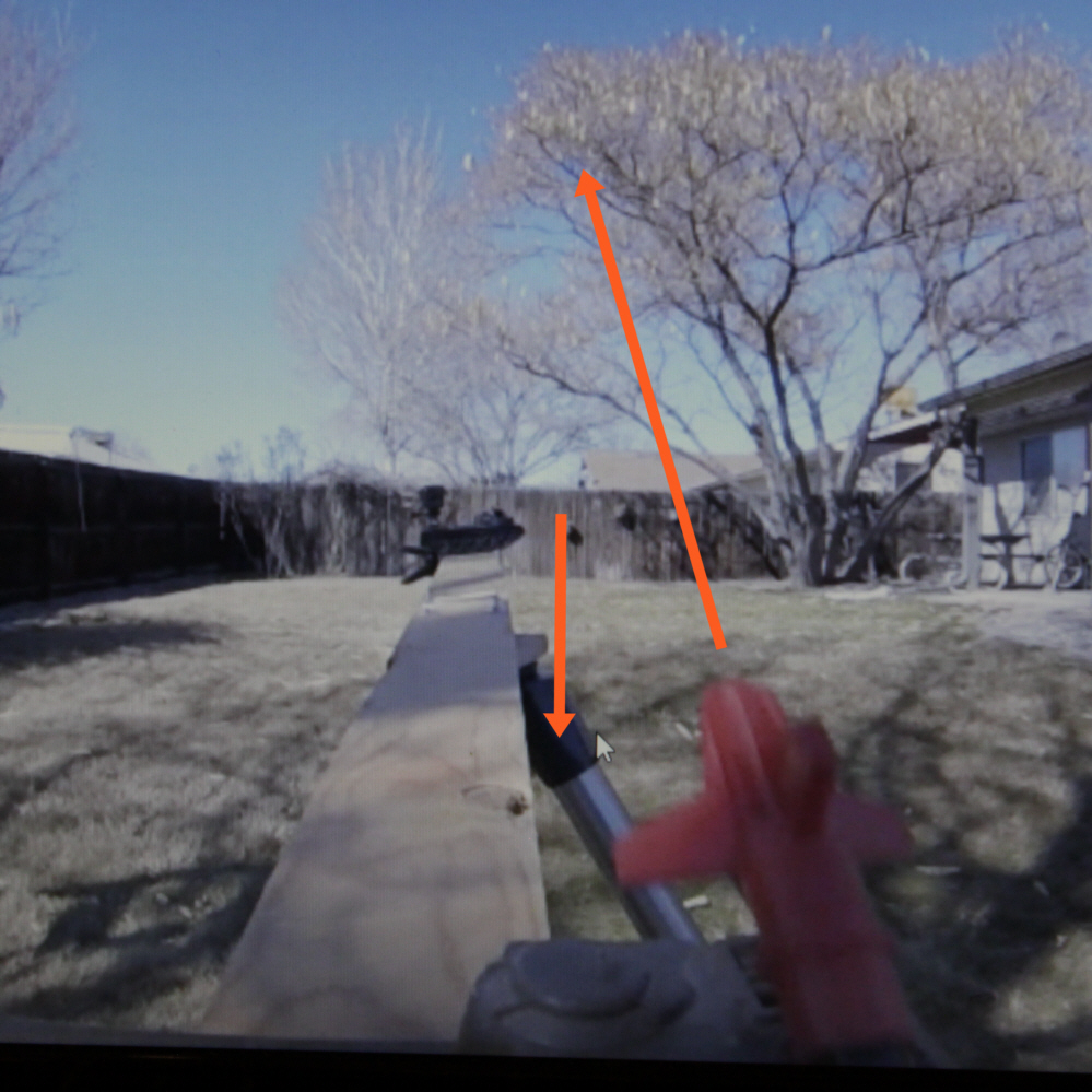
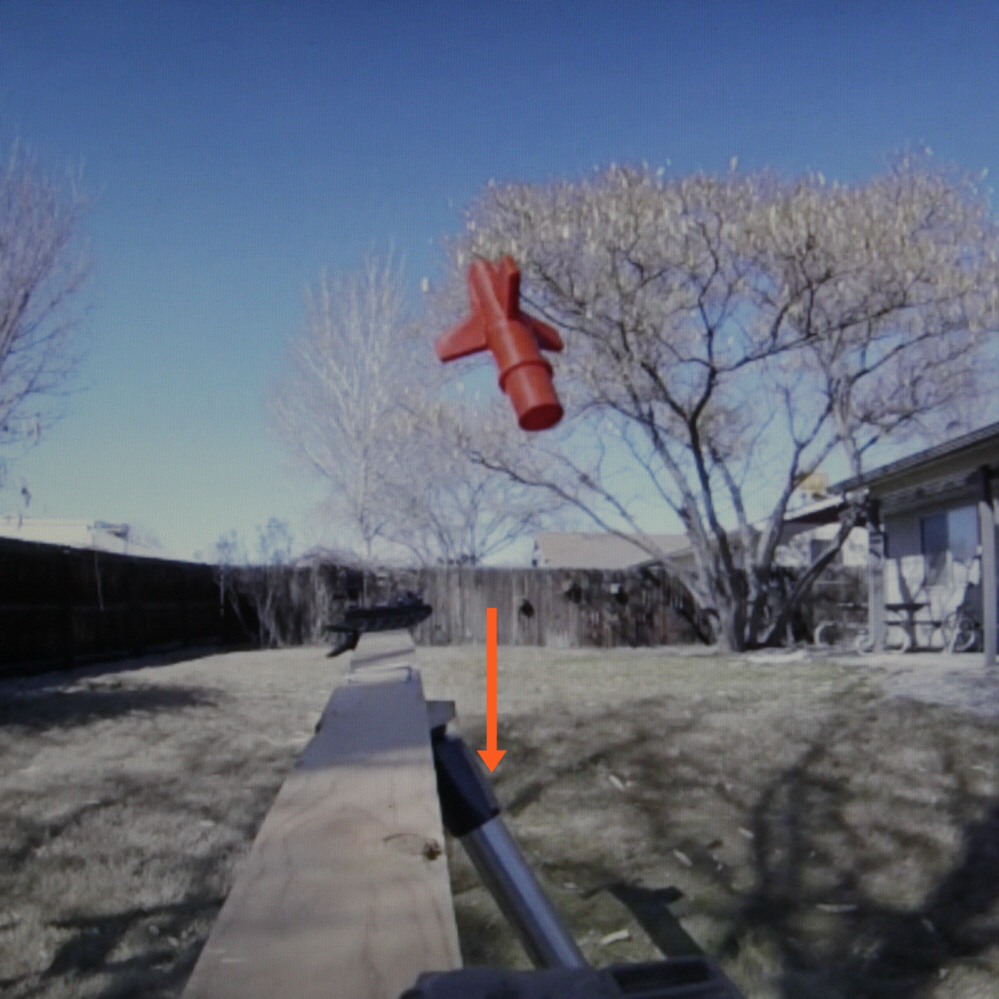
Let’s say you want to throw a sandwich to your fellow astronaut. Will it go straight. You may have seen this experiment on the internet. A good correlation is to picture yourself on a rotating carousel or merry-go-round. I wanted to perform this experiment for myself but because of safety issues, all merry-go-rounds have been removed from our area. That left me to search the garage for items I could use to make my own. It would be too small for me to ride so I had to find a way to launch a ball or other projectile and be able to film it from different points of view. An old toy from the 60’s and my action cameras did the trick. Next, I attached a board to a bearing I installed to an old telescope mount. I triggered the missiles with strings and spun the carousel by hand.

I spun the board by hand, fired the missiles and watched the result. I slowed down the video to make it easier to see the effects.
As you can see the missile curved. It actually went straight to the outside world but the rotation of the carousel makes it look like it curved. So what is happening?
It seems to curve to the right if it is rotating counterclockwise, left if clockwise. This is the essence of the Coriolis Effect. Why? For now, we will ignore the path the ball (or missile) takes during the throw or launch. We are interested in its final velocity when it leaves the hand or launcher. If you would like a description of what is happening during the act of throwing or launching, see the following paragraph. Otherwise you can skip to the next paragraph.
The best way for me to describe the path during the motion of the launch or a throw, is the missile or ball is making a new curved path that is being acted on by centrifugal force but in a new circle. It is a combination of the rotating merry-go-round and the motion of the arm while throwing (or launch). This motion would look like an arc from outside, creating a new force where the hub is now where the center of this new arc would be. When the ball leaves your hand, it is as if it lost the constant acceleration making it curve and is now traveling in a straight line with the velocity you gave it plus any velocity added by the rotation. The ball will travel in a straight line now with a constant velocity.
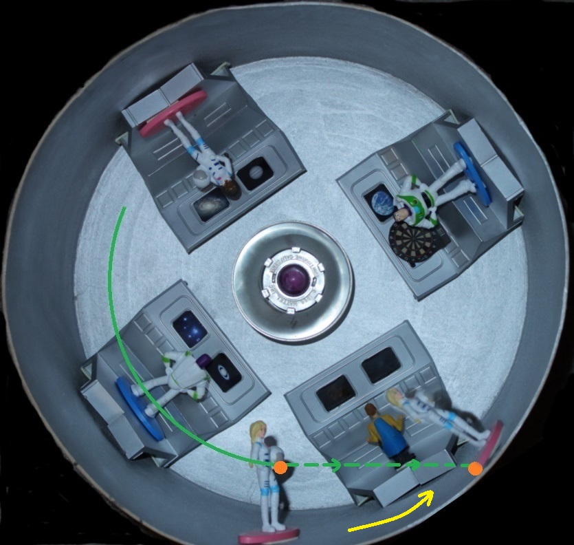
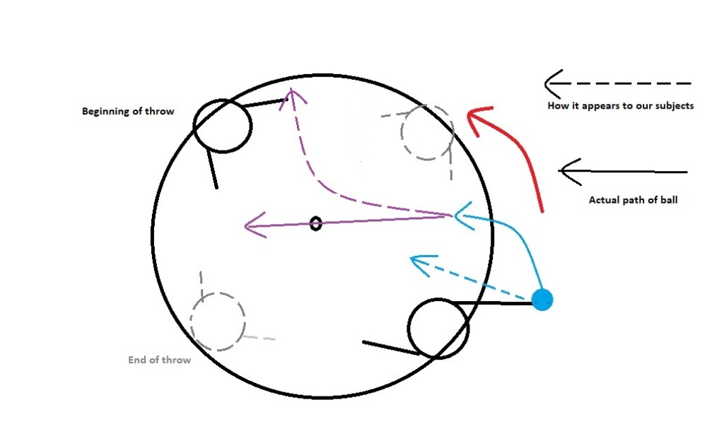
As soon as the ball or missile is thrown or launched, all the forces have combined to give it its velocity. The direction is the result of these forces. We will cover that shortly. After the throw (etc.) the ball will move in a straight line as seen by anyone outside the carousel but the people on the carousel will continue to rotate and the ball will appear to them as if it is curving. This is the essence of the Coriolis Effect in a rotating field. Below is a representation of that effect. The person at the four o’clock position throws the ball starting at four o’clock. Ball leaves the hand at three o’clock (the ball is taking a curved path during the throw, even if the arm makes a straight throwing motion). Ball leaves the carousel at the nine o’clock position but would look to the people on the carousel that it curved to the right, leaving somewhere between the two people.
How about some stopmotion to show the effect from the point of view of our astronauts.
In a drop, the circular motion ends and the inertia from that rotation is still in play, making the ball continue on the last path it was on when it was released. In a throw, your arm motion is making a new curve or rotation that has a different end. The velocity from the rotation and the throw are now added together so the ball will go faster (more on this in a moment). In the carousel examples from the internet, the throw is much faster than the rotation so the added velocity is not apparent. In a faster rotation, the added velocity is noticeable. One caveat is that if you throw against the rotation, the rotational velocity is subtracted. Here is my test showing this principle.
The amount of added or subtracted velocity depends on the angle. I measured a few from different angles and these are my results. Average distance launched from the toy launcher was 94 inches (2.39 meters). With rotation it was 179 inches (4.55 meters). Against rotation it was 36 inches (.9 meters). At a 45 degree angle it was 152 inches (3.86 meters). This demonstrates that the effect from the rotational velocity reduces as the angle approaches a 90 degree angle to the rotation. At 90 degrees, the rotational velocity is negated as far as I could measure. I learned a little vector mathematics at this point and the results are depicted in this diagram.
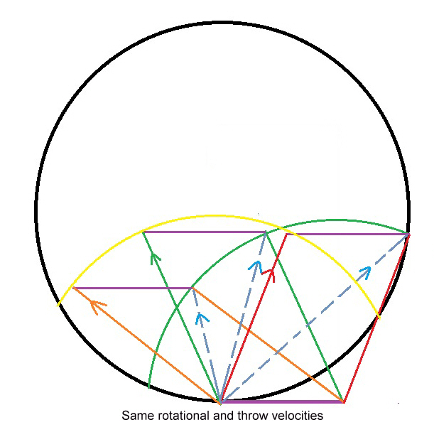
This diagram represents various throws at different angles from the direction of rotation. Each same color parallelogram represents a vector (see my article on “Calculating Angle and Velocity of Vectors in a Rotating Filed.”
The colored arrows on the left side of the parallelogram represent the throw velocity and the rotation’s influence on the throw is represented by the the right side line, which gives us the final vector angles and velocities which are represented by the dotted blue arrows. The yellow arc represents the relationship between angle of throw to the point of release. The green arc represents the final vector relationships. Throwing backwards subtracts the velocity of the rotation of the thrower. The equations, diagrams and method will be covered shortly. (Also see appendix 2).
Note: I performed more tests on March 27, 2022 and these effects were verified but there was a definite added lateral movement. The little missiles went pretty close to where they were aimed with a little noticeable lateral motion. They also had the predicted change to their velocity as the rotation added energy. A throw into the rotation added velocity to the throw. As the velocity of the throw decreased and the velocity of the rotation increased, the lateral movement increased. (See *Update below).
This is what I learned. My little missile launches at an average velocity of 15 feet per second. With a rotation of 6.8 ft/sec a launch resulted in a final velocity of 22.4 ft/sec (predicted velocity was 21.8). It diminishes as the angle approaches a 90 degree angle to the motion where at 90 degrees there is no added velocity. As it passes 90 degrees it diminishes the velocity. When launched in the opposite direction to the rotation, the velocity is reduced by the exact amount of the rotational velocity (as an example, the rotation was 6.4 ft/sec and the missiles launched at 15 ft/sec. The missiles traveled at 8.8 ft/sec. Within measuring errors again). I applied vectors to these tests and can graphically demonstrate the math. Vectors show that the lateral movement from the rotation gets stronger as the ratio of the velocity of the rotation grows in respect to the velocity of the throw. I still would like to perform this test on a merry-go-round, though.
The throw directly at the hub was a problem. I found that my tests could not accurately demonstrate the results from the vector analysis, evidently due to the varying conditions of the toys, wind and launch string. I then started predicting where the projectiles would land and found that those launched with the rotation were easy to predict. The ones against the rotation (or in the opposite direction of the rotation) were off by several degrees. Here is a test that the prediction was for the projectile to land in the bucket. I worked very hard to get the little tank to launch at the extreme right but it launched about 30 degrees too early. Here is the result in slow motion.
It launched early but still landed in the bucket.
There is a miscalculation somewhere. Until I can perform this at a larger scale, I cannot be certain of why it landed farther to the left than it was supposed to. Again, it was supposed to launch at the extreme right at the 3:00 o’clock position (from our point of view) and land at about the 12:30 o’clock position in relation to the launch (9:30 to us). Instead it landed at what was the 10:00 o’clock position in relation to the launch. My best guess is the launch was at a different velocity than predicted. Other possibilities include the breeze I had to contend with and the aerodynamics of the projectiles. (See Update 1/14/26 below). So how did I calculate this? Vectors. I had to teach myself vectors. Joy.
* Update
After considerable analyzing of the original video, I have found that the velocities were different than I had predicted and measured at the time. The carousel slowed more than I had originally calculated and the little tank had launched the missile at a slightly higher velocity. Doing the original calculations again, if we start with the angle of launch at 38 degrees (which is less than the 45 I had used in my original calculation which is the largest discrepancy) and more accurate estimated velocities of 8.6 ft/sec for the rotation and 10.3 ft/sec for the missile. Recalculating I get an original missile velocity of 15.67 ft/sec (very close to my original tests of the tank). This results in a final velocity of about 10.3 ft/sec and a final angle of 70 degrees. Very close to what we see in the video.
I want to perform more tests but the carousel was dismantled. I may make a larger version this spring. A carousel using an eight foot board is possible but I would need a more reliable launch mechanism and a way to gauge the rotation more accurately. Feel free to tackle it (either mathematically or physically) yourself and let me know what you find.
This next section contains quite a bit of trigonometry. If you wish, you can skip to Results of throw below.
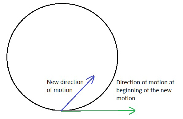
To calculate the new vector velocity, we need to know the original direction of the rotation. In this graphic we have the circular motion represented by a circle. The rotation direction and magnitude are represented here by the green arrow and the new motion is designated by the blue arrow. The new direction and motion can be in any direction inside the circle. The angle from the green line is theta.
To calculate what the new direction and velocity will be, at least two of these values need to be known. The rate of rotation, the new velocity from the change in direction, or the angle of the new direction in relation to the direction at the time of the change. The following diagram will be the basis for our equations. Our goal is to predict the purple dotted line and its value. Each line is a representation of a velocity. For example, in our first diagram the green arrow might be in feet or meters per second. To designate the value of each arrow, we will assume that it is a period of one second. If the velocity of rotation is 15 feet per second (ft/sec), in one second it will have rotated 15 feet. The green line would be 15 feet long. If the blue line was 9 ft/ sec, then it will be 9 feet long. We are interested in the velocity of motion only at the moment the item is released.

We will apply our equations to the diagram above. Line BE is the velocity of the rotation. Line BA is the new motion which could be a throw, a jump or a stride. The blue theta is the angle away from the rotation at the instant of the change in direction (usually designated as D). The purple theta will be the new angle after the forces average out.
Note: (Dec. 28, 2025) As stated above in the launch of my missiles, there is an added lateral force at work during the act of throwing. I will assume, for simplicity, that the person throwing the sandwich is accounting for this force as they throw the sandwich, making the angle and velocity of the throw as stated in the example as it leaves their hand. As with the launch of the missiles, we can calculate what effect the rotation has on the motion of throwing, but let us leave that for another time.
Example: A smaller spaceship with a diameter of 15 meters is rotating to produce 1/6 G or one lunar gravity equivalent. It is rotating at 3.5 meters per second, taking 13.464 seconds to rotate. An astronaut on board wants to toss a sandwich to a fellow astronaut several feet in advance of the rotation. One meter above the floor, the astronaut tosses the sandwich at an angle form the floor of 35 degrees a meter above the floor. The velocity of the toss is 2.9 meters per second. Where does the sandwich go? At one meter above the floor, the rate of rotation is 3.03 meters per second. To calculate this, first we have to find line DF above, then we can calculate BD, which will be our final angle and velocity.
Line BE is our rate of rotation or 3.03 MPS. Line BA is our toss of 2.9 MPS and theta is 35 degrees. Line BA and line ED are equivalent so line ED is 2.9 MPS (actually the meters per second will all be one second in length, leaving us with just a distance in meters). We first calculate line DF. We use this equation to calculate DF.
Sin 35 (ED) = DF
The sine of the angle of 35° = .573576. The length of ED = 2.9 (2.9 MPS x 1 second = 2.9 meters). .573576 x 2.9 = 1.66337. Line DF is 1.66337 meters (MPS). The sine of the angle (theta) multiplied by the line DF gives us the “height” of our triangle. Next we calculate the length of EF.
Cos 35 (ED) = EF
The cosine of the angle of 35° = .819152. ED = 2.9. .819152 x 2.9 = 2.37554. The length of EF = 2.37554 meters (MPS).
Next we add lines BE and EF to get the line BF. 3.03 + 2.37554 = 5.40554. Line BF = 5.40554 meters. To calculate line BD we can use the Pythagorean Theorem. BF2 + DF2 = BD2.
5.405542 = 29.2198629. 1.663372 = 2.766799757. 29.2198629 + 2.766799757 = 31.98666266.
√31.98666266 = 5.658675261. Line BD is about 5.66 meters long or the velocity of the toss is about 5.66 MPS. Next we need to calculate the angle of the toss.
Line DF / line BD = tangent .293850425. On a calculator, enter tan-1, .293850425 = 16.38072164 degrees. The final throw is about 16.38 degrees from the floor at the time of the throw, and about 18.6 degrees to the right of the angle of the throw (35 – 16.38072164).
Results of throw
The sandwich would travel at an angle of 16.38 degrees at 5.66 MPS. The velocity of the rotation and the velocity of the toss would equal a velocity in relation to the outside world of 5.66 MPS. Inside the rotating ship it would travel at 2.63 MPS in relation to the astronaut (but with an acceleration as described in the drop above). He also would miss his target.
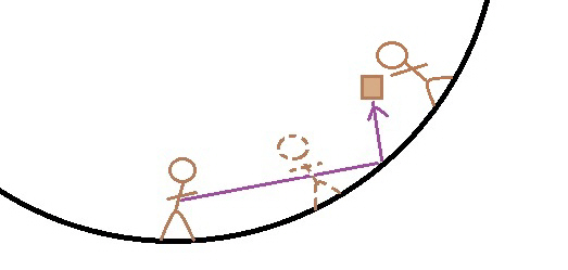
The dotted line figure represents both where the catching astronaut was at time of the throw and the throwing astronaut after one second. Our astronaut would miss his target (and hope for a bounce).
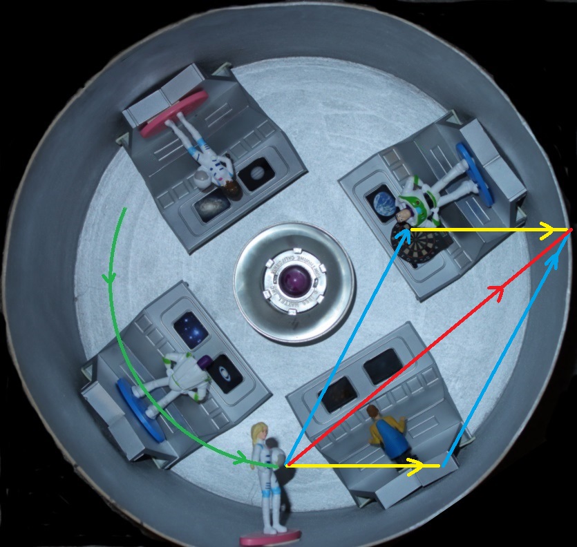
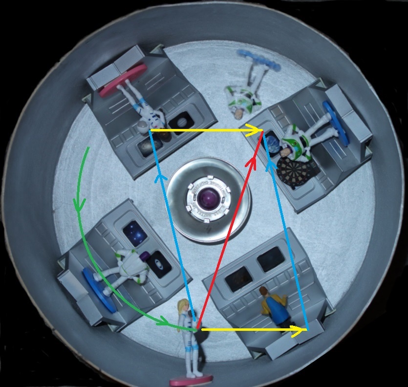
Ship view of a throw from Barbie to Buzz. Blue line from the figure is the intended throw. Yellow line is the force added to the throw from the rotation. Red line is the actual direction of throw after application of all forces.
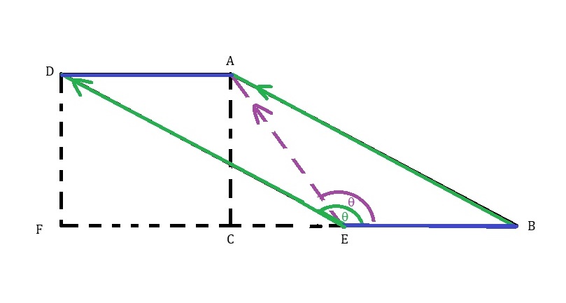
Now let us see where a throw against the rotation would go. This is a diagram of a throw in the opposite direction. (Again you can skip to Results of throw).
It is almost a mirror image of the previous diagram. In this one, line EB is the velocity of the rotation, line ED is the velocity and direction of the throw. Line EA is our final velocity and direction. You may notice that if the throw approaches the velocity of the rotation, line EA will move more to the left as line ED lengthens as does line EA. The lower the velocity the throw moves more to the right. If the angle moves more to the left, the final angle does move considerably. As the angle of the throw (blue theta) moves farther left (increases), the final (purple theta) angle approaches straight up, .
Again, we know the angle of the throw (blue theta), the velocity of the throw (line ED) and the velocity of the rotation (line EB). Again our goal is to calculate line EA which is the hypotenuse of triangle EC, AC, EA. First we need to find the length of line FE (which is equivalent to line CB).
We need figures again. We will use the example above for our example here. This time our astronaut is throwing the sandwich the other direction at the same angle from the floor at point of throw or 35 degrees and at a velocity of 2.9 MPS. Her hand is rotating around at 3.03 MPS again.
To find the angle (blue theta) we need to subtract 35 from 180, which results in 145 degrees but we will be using the 35 degrees to find line EF.
Sin 35 (ED) = DF
and
Cos 35 (ED) = FE
Sin 35 = .573576, line ED = 2.9. .576576 x 2.9 = 1.66337. Line DF is 1.66337 meters again.
Cos 35 = .819152, line ED = 2.9. .819152 x 2.9 = 2.37554. Line FE is 2.37554 meters long. It is the same as the first example but from here on it will diverge. This time we subtract line FE from line EB to get the length of line EC. Line EB = 3.03, therefore 3.03 – 2.37554 = .65446. Line EC = .65446. We can use the Pythagorean Theorem. EC2 + AC2 = EA2. .654462 = .42832. Since AC = DF, then 1.663372 = 2.7668. .42832 + 2.7668 = 3.19512. √3.19512 = 1.78749. Line EA = 1.78749 meters or MPS over one second again. Next we need to calculate the final angle of the throw. AC/EC = tangent 2.54159. Again using a calculator, tan-1, 2.54159 = 68.5226 degrees.
Results of throw
The sandwich would travel 1.78749 meters in one second at an angle of 68.5226 degrees to the rotation at the instant the sandwich is thrown. Here is a graphic representation of the throw. The dark purple arrow is the intended throw. The light purple arrow is the actual direction the sandwich would travel when the rotation adds direction and velocity to the throw. The left figure is the intended target astronaut. The middle figure is the thrower at the time of the throw and then the target astronaut at the end of the throw. The dotted figure is the final position of the thrower. The sandwich would would fly over the thrower’s head. He may catch it eventually as they rotate around and the sandwich travels straight to the other side of the ship.
If you throw across the ship (as in towards our perspective or away) they would have the same added or subtracted velocities. Also, the sandwich would curve in relation to the people inside. It would look similar to this view from my carousel.
This is how it would translate to the spaceship. The aim would have been directly at “Buzz” but the rotation would add energy to the throw and change its direction.
Ship view of a throw from one Barbie to another, in the backwards direction. The throw would go more towards Buzz, who would have rotated away from the throw..
Update: Here is a new vector diagram showing a backwards throw at a shallower or lower angle where the final angle remains in the general direction of throw. I am working on an animation to demonstrate this. The animation will be a new diameter and velocities, based on Clark’s description of the Discovery living space (35 foot diameter, ten second rotation).
The video I am working on will feature the view below (life issues have kept me from finishing the video but I am close). The Purple arrow is the direction and velocity of the original throw. The green arrow is the actual throw after the change in vector from the rotation. The black arrow is how it will look to the astronauts, demonstrating the Coriolis Effect. With a slower throw, our astronaut could catch his own throw.
The throwing astronaut is actually an image from one of my first Halloween costumes. About 1963 or 4.
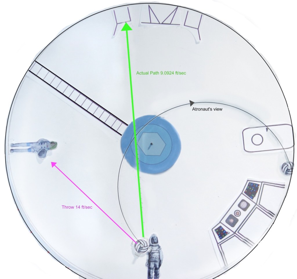
New Video of Backwards Throw
This was quite a project! Since I am not an animater or an artist but a photographer who dabbled in stop motion animation back in the 70’s, I had to do this as a drawing with cut out astronauts on a rotating sheet of paper. This would be a ship, 35 feet (10.67 meters) in diameter, rotating in ten seconds. The throw would be directly at Barbie (40 degree angle) at 14 feet per second (4.26 m/s). Using my vector method, I calculated the final angle and velocity would be 82 degrees at 9.09 feet per second (2.77 m/s). At that rotation, the G-force would be about 1/5 G. Here is my animation of the throw.
Here is how it would appear to the astronauts.
This vector method was double checked with three other people and is very accurate in most of my tests. Again, I think the differences were because of inconsistencies in the velocity of the projectiles due to length of launcher, age of spring and wind, as well as the possible added vector during the act of launching or throwing. Where’s a merry-go-round when you need one? Let’s move on.
Walking
Could you walk? Remember that as you step forward on Earth, gravity pulls your foot down (with an apology to Einstein). Here, as you step forward, the floor is coming up to meet your foot. May sound the same but it is not. As you step forward, nothing is pulling your foot down. You will have to lean forward enough so that your center of gravity is forward and then, you will tip over and the floor will come up to meet your foot. If you maintain a center of gravity that is not forward, your foot will remain in the air and you will not go anywhere. If the rotation of the ship is slow enough (such as a G-Force of 1/6th Earth gravity or equivalent to lunar gravity), it would all seem to be happening in slow motion. To walk, you will have to lean into where you want to go, step with as small of a lift to your foot as possible and wait for your body to pendulum or teeter over and down to the floor so you can repeat the process with the other foot. It should maintain the same process no matter which direction you are walking (at a right angle to the rotation, a lean into the direction of rotation would be need).
I read somewhere that if the ship is smaller with a reduced diameter, the Coriolis Effect would be magnified. Also, you would get a reduced velocity in rotation for a desired G-force. That means your head is getting a much reduced G-force than your feet (exaggerating the Coriolis Effect). It may add a lean to your walk. It may make your body want to trail your feet. I have not addressed this aspect and will let it go for now. A large ship like a 100 meter ring the effect would be negligible.
Running
Next we will tackle the problem of running. I have not seen or read of any application of this on the internet and most of the written articles focus more on the equations than on the effects. They also are more interested in weather patterns. More is covered in Appendix 4.
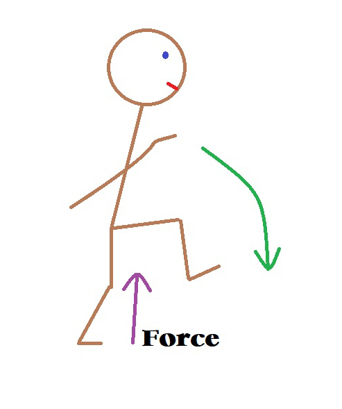
Okay, our astronaut wants to run. On Earth when we run, we go up in the air a bit and gravity pulls you down (excuse me Einstein) for your next stride.
When you push off in the ship, you travel in the direction of your push off and on a line that is the balance point of your body in relation to that push off. You also get an added “push” from the rotation.
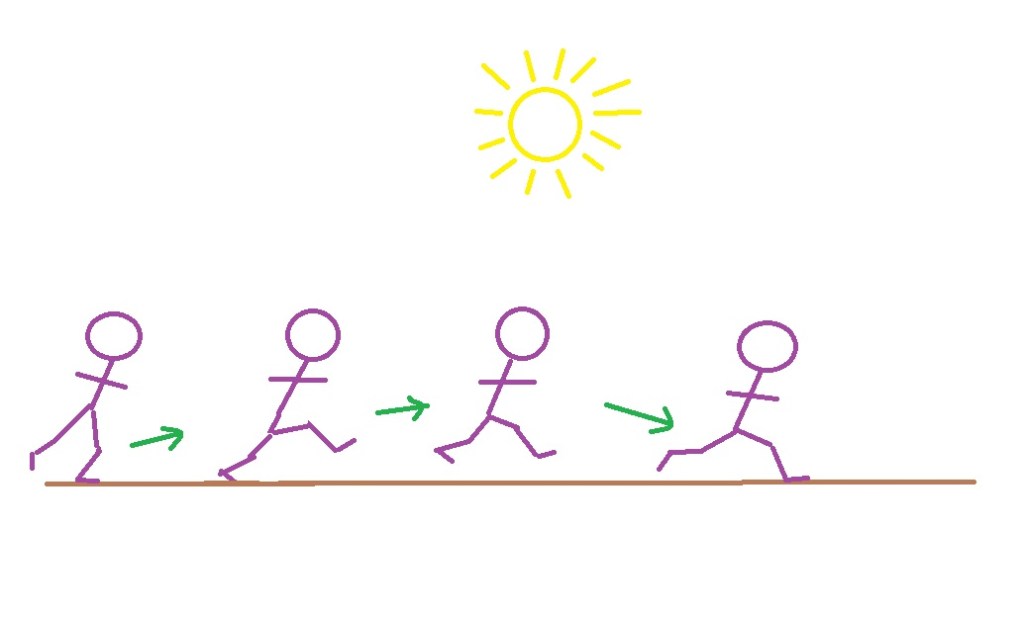
It is like throwing the ball. Let’s start with running in the direction of the rotation. If her feet leave the floor she will travel in a curved path in relation to the floor but in a straight line to the outside world and in the general direction of rotation but she will have to wait until the floor curves up to meet her. She may even land on her head if she pushed off or jumped hard enough. Here is a graphic representation of her “run.”
This is what it may look like.
If she runs in the opposite direction, the effect is compounded by her pushing off and her speed is subtracted from the ships rotational speed. Also a run in this direction actually decreases the magnitude of the gravitational component. This adds some new issues covered later and in Appendix 4.

Don’t forget your “center of gravity” determines your trajectory. Somewhere near your waist is your balance point. When you push off with your stride, your center of gravity better be in the direction of your run or your feet will propel you into a backwards somersault! Going “heals over head” might be fun. It also might hurt upon “landing!”
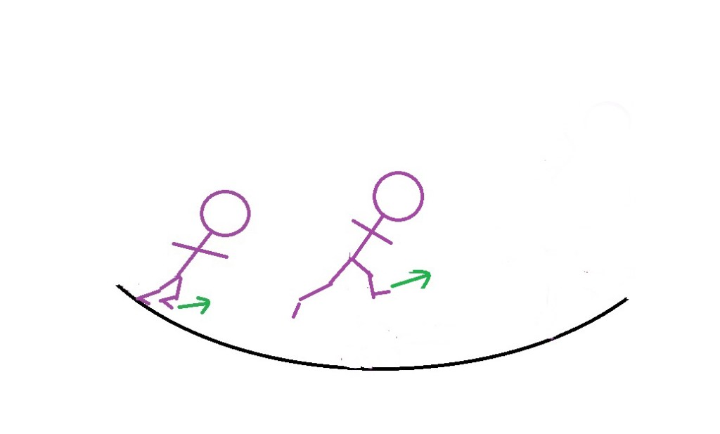
If she runs at a right angle she will find herself slowly moving away from the floor and the rotational energy will add to her direction. She will seem to rotate in relation to the ship. The graphic below shows this issue. She would have rotated in relation to the ship (not to the rest of the universe). Her direction of movement is away from our point of view.

The action of your legs and feet in the process of a run or jump are the same as your arm in a throw. The energy of the rotation is added to the velocity of the stride (subtracted when against the rotation). At least it would keep you in the general vicinity of the last stride and move you forward in your run. It would not in a jump as a jump would take you too far away from the “floor” to have any control on your landing.
CRASH!
I would recommend only jogging in the direction of the rotation and find an angle leaning forward that lets you balance out the rotation of your body with the floor as it seems to come up to meet you. I imagine it would feel like you were running uphill.
Running against the rotation is not the same!!! If you run in the opposite direction of rotation, you are lowering the gravitational equivalent force and may find yourself hovering while the floor passes beneath you. Also, the vectors we described earlier in a throw apply here as well. You aim your stride up too far and you will not meet the floor in time for your next stride. I call this stride that is aimed up from the horizontal the “Stride slope.” Next we will delve into running on a rotating ship.
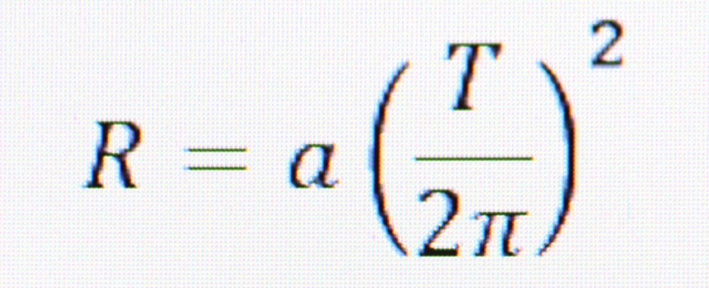
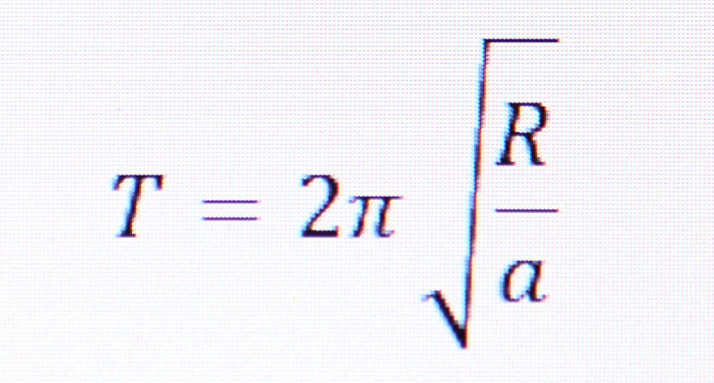
A great example of running in a rotating ship was shown in the motion picture “2001: A Space Odyssey.” Actor Gary Lockwood was seen jogging around a rotating ring inside their interplanetary space ship. The author Arthur C. Clark wrote the book and co-wrote the screenplay with Stanley Kubrick the producer and director. They described the ring as being a centrifuge that was 35 feet in diameter. It was rotating at one revolution in ten seconds. Using an equation we can calculate velocity of rotation and the gravity gradient we will calculate in feet this time since they did in the book). To calculate the radius of a spinning ring to get a desired acceleration, the equation is the acceleration, “a” is equal to the velocity (“v”) of the rotation squared, divided by the radius (“R”). Written as: a = v2 / R. Also, this equation works very well. You may not know the velocity. It is neatly tucked into the equation.

Where “R” is the radius, “a” is the desired acceleration and “T” is time in seconds. If you know the radius and the acceleration you need, to find the time necessary to spin the ship to achieve that acceleration, the equation is:

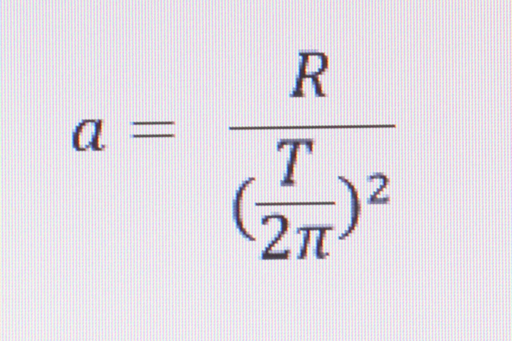
In this case, though we know the radius and the time. To calculate the acceleration use this equation:

When we plug in our know values we get an acceleration of 6.908723081 ft/sec2. One fifth Earth gravity (G) is 6.4 ft/sec2 so a spinning spaceship would experience about one fifth “G” at this size and rate of spin.
In the movie, character Frank Poole was jogging around the circumference of the centrifuge. I estimated his jog at a speed of 4.6 MPH which is about 3.13636 ft/sec. The centrifuge is spinning at 10.995574 ft/sec. We will round off to 3.15 and 11 for now. A jog in the direction of spin will be calculated first. This has a large difference between spin and jog. The angle of the slope will be arbitrary. The curve of the floor during one stride is close to about 5 degrees. I’ll save you the time. With these figures, the angle of slope is less than one degree and the difference in distance was less than 1/1000. It would seem perfectly normal. The movie was quite accurate.
I also calculated a run of 10 MPH which is 14.66667 ft/sec. A person running in this type of centrifuge could change their angle quite easily to adapt to the curvature. I will calculate an angle that slightly anticipates where a stride would take them with a curvature of a ship this size. 10 degrees is a good guess. In this case our final location of our runner after one second puts him outside the centrifuge. Our astronaut would stumble. We will have to rethink this. Anticipating the distance we estimated after one second would put our astronaut nearly one quarter of the way around the centrifuge. This time I will do the calculations for a run of 10 MPH and a slope or stride aimed up about 45 degrees.
This is a graphic representation of our calculation with these figures.
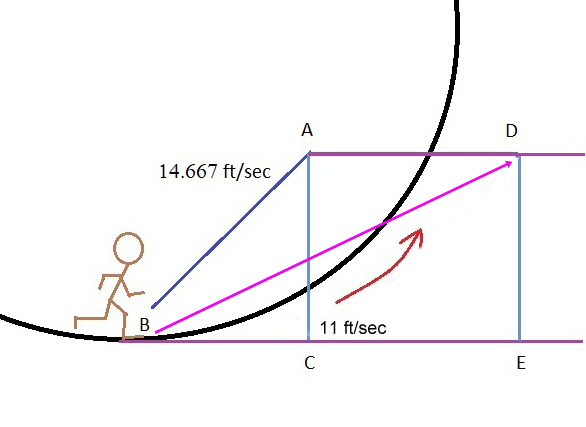
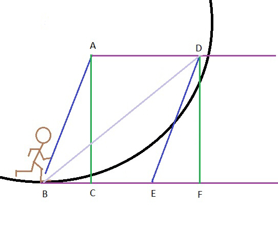
This is much better as his stride is closer to the floor. “D” is outside the circle after one second but this will make it feel like running uphill. All our astronaut would have to do is adjust the body angle to compensate. What would happen if we try a 70 degree stride slope?
Line DF (also AC), sin 70 x line ED: sin 70 = .939692621. .939692621 x 14.667 = 13.78247167. Line DF and AC = 13.78247.
Line EF = cos 70 x ED. Cos 70 = .342020143. .342020143 x 14.667 = 4.949031474. Line EF (BC) = 4.949.
Next we add lines BE and EF to get line BF. We get 15.949. According to Pythagoras, DF2 + BF2 = BD2. Thus 189.1304311 + 254.370601 = 443.5010321. √443.5010321 = 21.05946419. Line BD = 21.06 feet. Theta B or the new slope angle is tan DF/BF = 40.832degrees. This is a graphic representation of where “Frank” would be if he had run at 10 MPH and stride was angled at 40.8 degrees to stay above the floor.
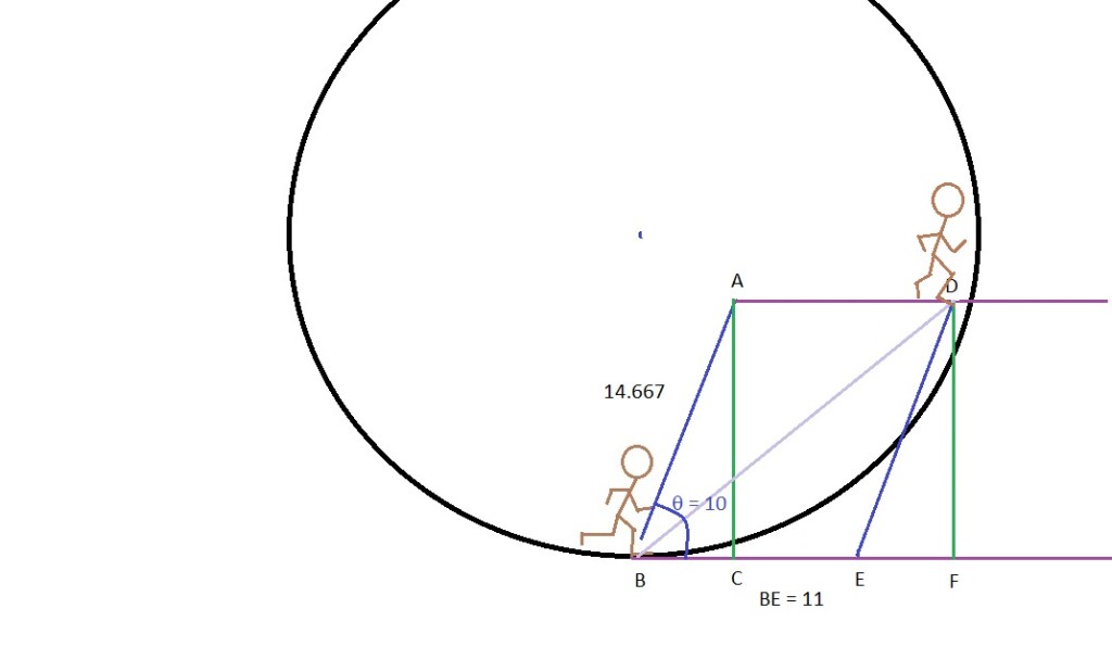
In this case in one second our astronaut meets the floor. The problem is there would be two or three strides in mid-air before he meets the floor. I have over compensated. This is actually how you would calculate a jump. In reality, it would take practice to see what the stride slope should be with a normal running stride length and frequency. It should work nicely. An astronaut may take two or more strides per second and if they angle their body (lean back somewhat) they could be ready for the next stride and not land on their face. As you can see, a jump would be a problem. This is what it might look like with a stride slope of 40 degrees.
How about a run in the opposite direction?
We will calculate a 4.6 MPH jog to match 2001: A Space Odyssey. (You may skip to Results). Our diagram again is:

This time we will anticipate a drift up from the floor. We will select 15° as our slope angle. We will also choose one stride as our speed and distance unit. At 4.6 MPH, I calculated two and a half strides per second. That is .4 seconds per stride. All of our velocities will be 40% of the previous velocities. Our 4.6 MPH or 6.75 ft/sec is now 2.7 ft/unit time. Rotational velocity is now 4.4.
Sin (theta) x ED = DF. Cos (theta) x Ed = FE. theta = 15, sin theta = .258819. Cos theta = .965925826. DE = 2.7.
Then,
Sin (15) = .258819. .258819 x 2.7 = .6988.
Cos (15) = .965925826. .965925826 x 2.7 = 2.608.
AC = DF. DF = .6988. FE = 2.608.
EB – FE = EC. 4.4 – 2.608 = 1.792. EC = 1.792.
EC2 + AC2 = EA2. 1.7922 (3.211264) + .69882 (.48832144) = 3.69958544. √3.69958544 = 1.92343. EA = 1.92343. AC/EC = tan (theta new or theta2). .6988/1.792 = .389955357. Tan (.389955357) = 21.3°.
Results
To recap, one stride at a 4.6 MPH jog, with a 15° stride slope will result in a new angle of 21.3°. There is a backwards drift of 1.92343 feet. The ship has rotated 4.4 feet along its circumference which translates to 14.4°. 1.92343 feet from the rotation of 4.4 = about 2.5 feet, close to the stride length. The curvature would reduce that. Our astronaut would be the correct distance traveled for one stride. Unfortunately, our astronaut would be about a half of a foot above the floor and not able to take another stride. What this demonstrates is that a jog against the rotation would work with a proper stride. But too much of a push off will propel you away from the floor and you will not contact the floor for another stride. You may also land on your back.
The important point here is that after your stride, you will travel in a straight line to the outside world and will have to wait until the ship curves up to you before you land for your next stride. You will be rotating in relation to the ship as well and may land on your face.
Jogging in a rotating ship would not be a simple procedure unless the ship is huge and the angles of “stride slope” described above would be negligible. It can be done with practice but it would be easy to miscalculate and the resulting positions of your body as the ship rotates could be hazardous.
What are some of the other interesting things that our astronaut would experience? If the ship is small with a large difference in the force at small distances, your walk may need you to lean into, away from or at an angle to your walk. Running would be possible depending on your stride, your direction of your run and a possible lean in the direction of the run. You also could not run at an angle to the spin easily. You will be relying on the curve of the ship to rotate up to meet your feet. The velocity of the spin may make a big difference as shown in the next graphic.

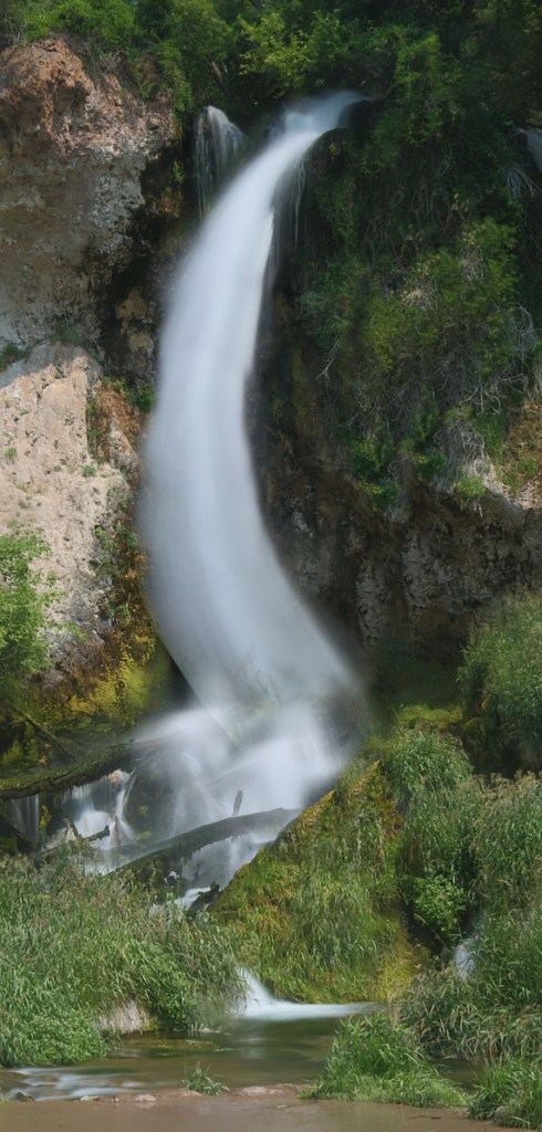
Waterfalls
Some interesting things come to mind.
In “Rendezvous with Rama”, Arthur C. Clark had a waterfall inside his rotating spaceship. Rama was HUGE! It was forty kilometers in diameter and rotated in four minutes. In Appendix 2, I discuss the equations for figuring the acceleration. It has been many years since I have read the entire novel but certain things have stuck in my memory. One was a waterfall. It fell in a curved path hundreds of meters and landed “three or four kilometers away.” His description of the waterfall was spot on. I am not surprised. This was the first person to calculate a geosynchronous orbit! Later he had one of his astronauts do a high dive but he did not mention the curve the astronaut would have made on the way down.
What would be awesome is if in a huge ship like this, the water began its “fall” at the hub. There would be very little centrifugal force to add velocity to the fall of the water so it would be better to shoot it out at a sufficient rate for it to make the trip more quickly. If you picked a “fall” of more than one rotation, it would curve all the way around the interior. Let us say you decided on a fall lasting eight minutes or two rotations of the ship. The water would come out and would make two complete spirals as the ship rotated, landing directly beneath the “spout.” Picture it! The water leaves the hub, makes a spiral down to the “floor” and hits at whatever rate they decided to shoot it out of the pipe “above.” It would hit the same spot every time and look like it was suspended in the air, not varying in shape or location. If it “fell” out of the hub, it would be a tighter spiral and would hit at a slow velocity, the velocity of the pipe at the opening, and would not accelerate on its way down making an extremely tightly coiled spiral all the way down. COOL! Think of the dropped ball. The water falls behind where it is “dropped” and travels a straight line as seen from outside but since the pipe is rotating, the water would spiral and since the floor and pipe are fixed, it is the same distance traveled no matter when the water is released. It would hit the pool below in the same spot but would take a cool backward spiral on the way down (backward to the rotation of the cylinder). Any air currents would cause it to slowly lose its original stream and should hit the “floor” more like rain but always in the same spot. I’d like to see that! Here is a simple graphic of what it would look like. Also pictured is an attempt to duplicate it on Earth. Description of how it was captured is in Appendix 3.

Maybe a video of the waterfall would help? The spiral travels away from the camera due to Earth’s gravitational field. In space it would stay on the same plane.
When we finally have a spaceship that rotates to simulate gravity, we will find out how accurate my calculations are. Will it make for some interesting games? Cause nausea? Or something I haven’t thought of? One thing is for sure, basketball will not be the same since the ball will curve drastically. The curve will be more pronounced the farther the shot. Depending on the direction of the shot, it may curve left or right (it also would not “come down” into the basket). A huge rotating ring would make all motions less pronounced since the difference in distance from the hub is reduced to a small percentage. You would be able to walk but running could be dangerous and a jump could be deadly since the ring would be rotating much more quickly at the outer edge. Kubrick’s “2001: A Space Odyssey” had a 900 foot ring spinning at 52 seconds per rotation. The outer rim is traveling at over 54 feet per second! NASA has announced a possible rotating ring in the future. Maybe they should read my article before they spend the money….
Appendix 1
A: The Coriolis Equation is: 2m(w x v) where m=mass, w is the angular velocity and v is the velocity relative to the rotating reference frame.
B: The equation for a rotating frame to achieve a desired centrifugal force is: a = v2 / r. Where a = acceleration, v = velocity, r = radius. Example. Radius = 22 meters. v = 22 x 2 x = 138.23 meters / 23 seconds = 6 MPS (meters per second). 62 = 36, then 36 / 22 = 1.63636… meters per second squared (Earth gravity or G is 9.8 MPS2). Approximately 1/6th G which is the equivalent to the G force on the surface of the Moon.

C: The equation for determining how far a dropped item would travel is the basic Pythagorean theorem: a2 + b2 = c2 , where a is the distance the item travels, b is the distance from the center hub of where the item starts its fall (radius) and c is the distance (radius) from the hub to the “floor” of the ship. Solving for a: . b = 20.4 meters, c = 22 meters, so b2 = 416.16, c2 = 484. 484 – 416.16 = 67.84. = 8.2365. Ball “falls” 8.2365 meters. Ball begins fall while traveling 5.573 MPS. Radius or distance from hub to ball = 20.4 meters. 20.4 x 2 x π = 128.17meters. 128.17meters / 23 seconds = 5.573 MPS. 8.2365 meters/ 5.573 MPS = 1.48032 seconds. Ball takes 1.48 seconds to hit the “floor.” To our astronaut it would travel a little over the 1.6 meters in 1.48 seconds (a curved path) at about 1.09 MPS. Also it would land .645 meters behind her (1.468 seconds x 6 MPS, minus 1.468 x 5.573 MPS = .645 meters). To be more exact, she would travel 8.88 meters along the circumference but the ball travels straight. After calculating the exact contact with the floor in relation to the astronaut, the ball lands .45 meters behind her.

To calculate how far behind you a drop would land in a rotating ship, you first need to calculate the distance traveled (line BC) during the “drop.” We will use the example from earlier. We calculated a distance of 8.23meters in 1.48 seconds. Here we want to solve “theta,” find the length of the two arcs and subtract EC from ED to get the length of arc, CD.
The orange “theta” is the angle made by the ball as it moves towards the “floor,” designated with an “A” subscript one. The green “Theta” is the angle made by the distance the “floor” has rotated, designated “A two” (which we will not need to calculate at this time). After calculating the distances and times in the above example, we then use this diagram and following equation:
From the earlier example, Line AB = 20.4 meters (M). Line BC = 8.23M. Line AC = 22 M.
Find Tan A1. BC/AB = Tan A1. Tan A1 = .403750202. On a calculator (or use a tangent chart), thus Tan A1 = 21.98640302 degrees.
Find the fraction of the circumference that Tan A1 is the quotient of. 360 degrees / 21.98640302 = 16.37375607.
Now find the distance of that quotient.
Circumference = 138.2300768 M. 138.2300768 / 16.37375607 = 8.442172719 M. This gives us the length of arc for EC.
Next find the quotient of the rotation divided by the length of the drop.
Rotation of 23 seconds / 1.47795293 seconds = 15.5620653. This gives us the fraction for Tan A2 or length of arc ED.
138.2300768 M / 15.5620653= 8.882502042 M. This gives us the length of arc for ED.
Next subtract length EC from ED which gives us the length of arc, CD.
8.882502042 – 8.442172719 = .440329323 M. The ball lands about .44 meters behind her. You can also calculate the green theta or “A2” to get the angle our astronaut travels during the drop which will also help you to find the direct line form the astronaut to the ball in a straight line. This would be helpful for calculating precise distances in a large ship like that proposed for the motion picture “Passengers.” To get that, the time of the rotation is 23 divided by the time of the ball drop, 1.47795293 = 15.5620653. 360 degrees / 15.5620653 = 23.13317629 degrees. So about 23 degrees.
Again, the curve of the drop is a constant velocity but would appear to accelerate away from the astronaut as she rotates away from the ball.
Appendix 2
A: 2001: A Space Odyssey: The rotating space station was described in the novel as being 300 yards in diameter or 900 feet in diameter (in 1968 they only thought in feet). It rotated once every 52 seconds in most scenes (in the novel, Clark makes no mention of the rate). This equates to a suggested equivalent to Earth gravity as 6.57 feet per second squared. Earth gravity is 32 feet per second squared. This would be equivalent to about 1/5th G (or 1 /4.87 of a G) less than Mars equivalent but more than lunar gravity.
900 feet x π = 2827.433 feet / 52 seconds = 54.3737 feet per second. 54.37372 / 450 feet = 6.57 feet per second squared.
The rotating living space inside the 700 foot long “Discovery” ship sent to Jupiter was described in the novel as 35 feet in diameter, rotating once every ten seconds. This equates to 6.9 feet per second squared, a little over 1/5 G (1/5.333). About the same (Clark stated that it would equate to 1/6 G but my math does not agree. If the centrifuge rotated in 11.396 seconds it would be 1/6th “G.” A difference we won’t dwell on).
35 ft x π = 109.956 ft / 10 seconds = 10.9956 ft/sec. 10.99562 / 17.5 ft = 6.9087 ft/sec2.
In the movie, the rates of rotation varied, probably due to production issues. The scene in which Dave and Frank step from the nonrotating hub into the rotating living ring actually appears to be rotating at 21 seconds per revolution which would make it 1.56 ft/sec2 or about one third lunar gravity. Kubrick probably thought no one would notice but it would have simplified the production issues, let alone less dangerous. In reality, it would be easier to float through a rotating tunnel (which is how Clark described it in the novel), then part of the way down the ladder in the centrifuge, before the perceived gravity became noticeable, rotate your body to descend the ladder.
The equations for determining the radius (R), times (T) and acceleration (a) is:
Solving for T (time):
Solving for the acceleration:
In my example earlier, I had a diameter of 22 meters. Let’s go at it from a different angle and in feet. If an acceleration or “a” = one “G” (32 ft/sec2); time of rotation or “T” = 30 seconds then the radius is 729.5 feet. Which is a diameter of 1459 feet (almost five football fields). I picked these parameters for 30 seconds of rotation to show how the diameter changes to get a desired acceleration.
If “a” = 5.3333 ft/sec2 (about 1/6 Earth gravity or Lunar equivalent) and “T” = 30 seconds, then the radius is only 121.585 feet. Which is a diameter of 243.17 feet (less than a football field).
Actual velocity of outer rim or “floor” is 152.79 feet per second versus 25.46 feet per second. A 10 MPH jog is 14.67 feet per second. If you tried to run in a rotating ship and you left the “floor,” you are no longer traveling the same velocity as the ship. You are traveling at the velocity that your stride gave you plus any from the rotation that diminishes with the angle of the push off from the floor. The discrepancies between your stride and the rotation of the ship grows with the angle. This could be a fatal mistake. Remember that when you throw a ball on a merry-go-round, the spin of the merry-go-round does not add to the velocity of your throw towards the hub, only at an angle. Another interesting thing is if you threw the ball at an angle and with less of a velocity of the merry-go-round, like almost straight up or behind the rotation and its velocity away from you was relatively slow, then the ball would curve the opposite direction to you. This is a test I would like to make but there are no merry-go-rounds in my area. See my theorizing in Appendix 4 on this aspect.
Note: To be precise, Earth’s “G” force at sea level is 32.174 ft/sec2 or 9.81 m/sec2. Lunar gravity is 5.32 ft/sec2 or 1.62 m/sec2 and is 16.5350904% or 1/6.047744361 that of Earth’s.
B: Rendezvous With Rama: It has been many years since I have read the novel so I can only describe a few things I have listed here. The cylinder Arthur C. Clark describes is a hollow, barrel shaped space ship from another solar system. The diameter was forty kilometers and rotated in four minutes. Substituting meters and seconds we have;
40,000 meters x π = 125663.706 meters / 240 seconds = 523.5988 meters per second. 523.59882 / 20,000 = 13.7 m/sec2. Earth equivalent in meters is 9.8 m/sec2. Rama was experiencing about 1.4 times Earth gravity at the outer hull. Clark said the center area was sixteen kilometers across, with an inside radius of eight kilometers. Inside as you stood in the artificial gravity from the centrifugal force, you would experience a G-force of about 55 % Earth gravity (.55 “G”).
Appendix 3
The image of the spiraling water was created by spinning a bucket at an estimated 240 rpm (using a variable speed cordless drill). The water is coming out of a straw that is bent at a 90 degree angle at the top of the bucket (below the funnel) and extends about one inch. Since the straw is rotating at the same rate as the rest of the bucket, one would think it would be a straight line all the way down but it is experiencing a different acceleration due to it rotating in a smaller circle. Thus it is traveling at a lesser velocity and cannot keep up with the rotation rate of the bucket. If there was not a bucket to catch the water, it would look like a sprinkler that is spinning and ejecting water in spirals (actually, there was a leak in the funnel and Pam and I were splattered with water like a sprinkler). As you can see, if the bucket was spinning at a perfect rate, the water would be a perfectly continuous column all the way down. The spiral gets more open as the water accelerates due to gravity as it falls to the bottom of the bucket, but if the view was directly from the water source, it would be a geometrically perfect spiral. In a weightless environment, it would also be a geometrically perfect spiral and remain at the same level (in this case at the top of the bucket) all the way to the outer rim as in my drawing above.
This is what is happening: As a water molecule leaves the straw, it loses its acceleration from the rotation and continues in a straight line directly towards the side of the bucket from the viewpoint of someone standing next to the bucket (such as me as I worked the drill) as described in the main text above (see carousel example). My calculations suggest it took one quarter of a second for it to hit the side of the bucket. In the meantime, the bucket made one complete turn. This translates to four rounds per second or 240 rounds per minute which also agrees with the rate targeted using the drill to spin the bucket. Gravity pulled (again apologies to Einstein) that molecule down and it hit the side of the bucket near the bottom about twelve inches below the spout. One Earth G is 32 feet per second squared and calculating distance, time and acceleration (d =A x t2 / 2 ), with A = 32 ft. /sec2, t2 = (.25)2 or .0625. 32 x .0625 = 2. Completing the math, then 2 / 2 = 1 or d = 1 foot. Water fell about one foot to the spot where it hit the bucket.
Water spout was spinning at 240 RPM. Radius is one inch. Velocity = distance / time. 240 RPM = four rounds per second. Diameter is one inch x 2 times π = 6.2832 inches. Figuring in feet, distance is 6.2832/ 12 = .5236 feet. So .5236/ .25 seconds = a velocity of 2.094 feet per second. Acceleration of a rotating field or the centrifugal force = velocity squared divided by the radius or a = v2 / r. So 2.094 2 = 4.3865 feet per second. 4.3865/ .4167 inches (10 inch bucket, radius 5 inches or .4167 feet) = an acceleration of 10.527 feet / sec2. Solving for t above: t = the square root of (2d/A). Thus .4167 x 2 = .8334. .8334 / 10.527 = .07922. Square root of .07922 = .2815 seconds. Time from spout to side of bucket = .2815 seconds.
Both calculations of the acceleration of gravity and acceleration of water from a spinning spout agree to within measuring errors. It took about .25 seconds to go from spout to the side of the bucket and about .25 seconds for water to fall one foot. Bucket made one revolution in .25 seconds. Final result, 240 RPM.
Whew. My head hurts!
Appendix 4
In “2001: A Space Odyssey,” Stanley Kubrick showed actor Gary Lockwood as “Frank Poole” jogging around a “centrifuge” that was located in the habitation section of the “Discovery” space ship. The centrifuge was rotating once every ten seconds which would create a gravity gradient of about 1/5th “G.” This diagram demonstrates what would happen if he has jogging at 10 MPH instead of the apparent 4.6 MPH depicted in the movie.
Applying our method to “Frank’s” jog but calculating for 14.67 ft/sec and a stride slope of 40 degrees, we get a new angle of 22.97877135 degrees at 24.15454581 ft/sec. This is what it might look like.
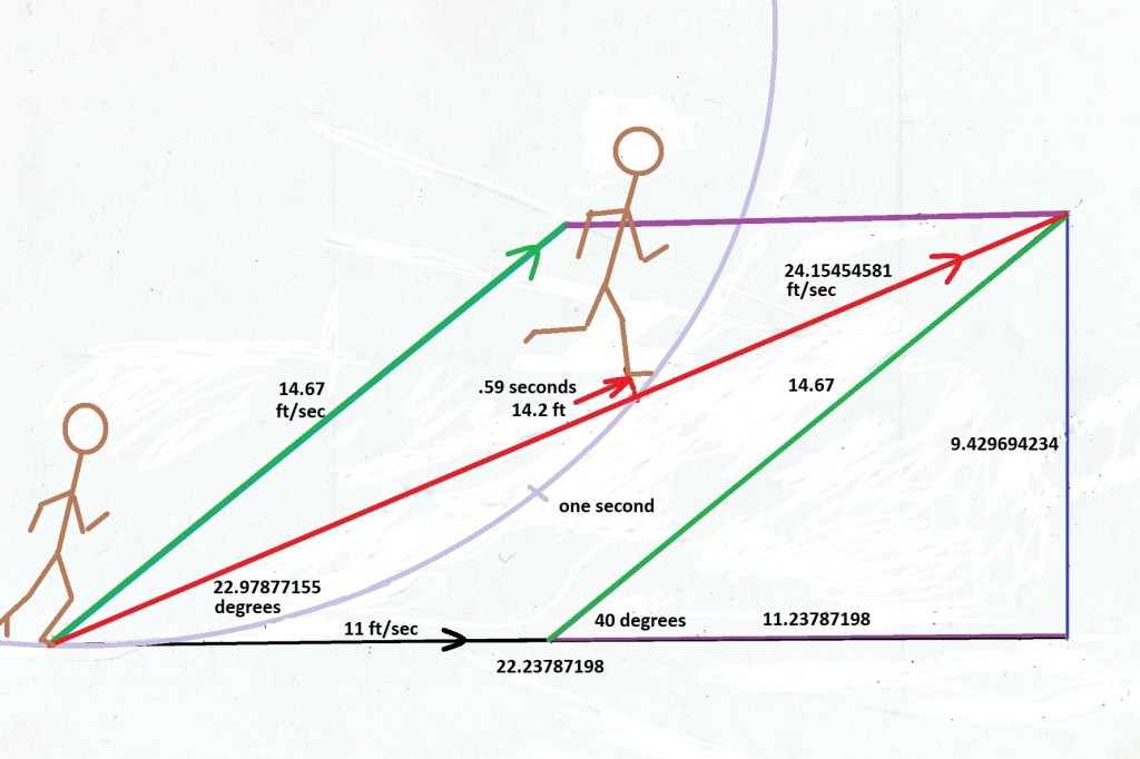
He would meet the floor after only .59 seconds, about 3.5 feet farther along the floor. He would also be tilted forward in relation to the floor. I wonder what a normal stride is for a man of his height at 10 MPH? I’m too old to run that fast and the equation I have used in the past for determining the velocity of a dinosaur from his tracks only works for walking (but that is another story).
Appendix 5
I made my own carousel from parts I found around the garage. I still have a box of old toys that I used for stopmotion animation back in the day and these tanks from a “Switch-and-Go” that I received as a Christmas gift in about 1966 still launch their missiles. I set it up with strings to fire all four missiles at the same time to save time but it didn’t work. I had to trigger them one at a time. This one experiment was to aim it as close to straight down the board as I could so we could see where the missile was aimed when it left the launcher. The angle would be the same as if it was fired straight up in our spaceship, which is the experiment I want to complete the most. I wanted to know if the rotation added any force from the rotation other than the velocity. My experiment shows very little “added lateral velocity” as I described it earlier, when the projectile has a much higher velocity to the spin (see updates above). There is also force added to the velocity of the missile. Another experiment proved that scenario, as a missile launched in the direction of the rotation gained velocity and landed much farther away than one aimed in any other direction. Those aimed behind did not go very far at all. In the videos, watch where the missile is aimed and where it lands. Also, the angle made a difference in the added velocity which makes sense as a throw more towards the center is at a 90 degree angle to the rotation and that would counter that velocity.
Update: There is a bit of lateral velocity noticeable here, but since the rotation is slow, the angle is small. After watching this video multiple times, I see that the missile leaves, aimed at the middle tree but lands more along the line to the right tree, demonstrating the added lateral force from the rotation, during time the missile travels along the launcher. Here is a graphic representation.

I still would like to try these experiments on a carousel or merry-go-round. I have made a few more tests to see if I can predict where the projectiles will go using my vector equations. I am very close when the angle is with the rotation but consistently overestimate the lateral component when it is against the rotation. The first issue is calculating the actual velocity of the projectile and I also have been fighting wind and air resistance. The second is calculating the lateral rotational force along the launcher during the act of launching.
Here is one where I predicted the projectile would land in the bucket but the projectile launched early and you can see what happened.
In slooooowwww motion.
As close as I can tell the rotation was 11.6 ft/sec. Projectile velocity was about 4 ft/sec. Missile aimed at a 135 degree angle from the direction of rotation and the final angle was 115 degrees . Distance from launcher to hub, 31 inches. I predicted it would travel at a 48 degree angle at 8.57 ft/sec. I am still trying to find my miscalculation. Best guess is my angle of launch was more than 135 degrees and that the velocity was not as fast as predicted. I also had a breeze but that would only affect the distance (no curve was detected from any wind).
Update 1/14/26
After considerable analyzing of the original video, I have found that the velocities were different than I had predicted and measured at the time. The carousel slowed more than I had originally calculated and the little tank had launched the missile at a slightly higher velocity. Doing the original calculations again, if we start with the angle of launch at 38 degrees (which is less than the 45, or 135 as measured above, that I had used in my original calculation – which is the largest discrepancy) and more accurate estimated velocities of 8.6 ft/sec for the rotation and 10.3 ft/sec for the missile. Recalculating I get an original missile velocity of 15.67 ft/sec (very close to my original tests of the tank). This results in a final velocity of about 10.3 ft/sec and a final angle of 70 degrees (110 above) . Very close to what we see in the video.
I have had some of my vector math double checked and so far they are verified. If I am missing something, please feel free to share. I am not looking for a degree just having fun with math.
This has been very difficult but also rewarding. I have learned a lot. I did a few calculations to see if you could play basketball as they did in the motion picture “Passengers.” I found that you could. The vector angle did put the ball “coming down” into the hoop in a few seconds but shooting into the rotation gives your shot more energy and less if against the rotation. I think it would curve if at a 90 degree angle to the rotation. May have to work on that. I haven’t learned vectors in three dimensional space yet. To quote Indianan Jones, “How hard can it be?”
Since writing this, I did calculate a three dimensional throw. Results are in my companion article “Calculating Angle and Velocity of Vectors in a Rotating Field.” The object thrown would curve in relation to the thrower and the resulting acceleration makes for a complicated path to show two dimensionally. I have mostly concentrated on the path in relation to a view from outside. Inside there will be a very complicated curve. I will work on adding views as seen from the thrower. Again, my diagrams will be simple.
I am anxious to hear other people’s views on these theories. Any experiments that you can suggest to prove or disprove anything is welcome.
Updated Dec. 28, 2025.
